Settings reference
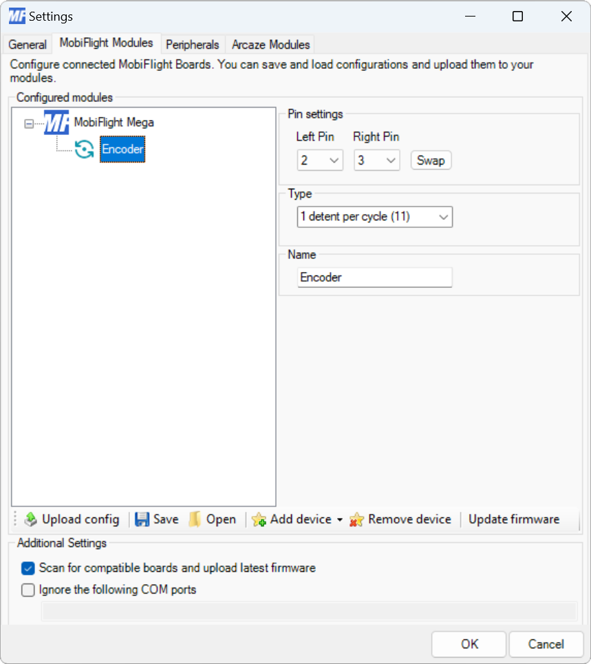
Modules dialog
| Setting | Description |
|---|---|
| Left pin | The board pin connected to the left output pin on the encoder. All digital and analog pins are supported. |
| Right pin | The board pin connected to the right output pin on the encoder. All digital and analog pins are supported. |
| Swap | When pressed, swaps the left and right pin assignments. |
| Type | The number of detents and data signal order of the encoder. 1 detent per cycle (11) and 2 detents per cycle (00, 11) are the most common encoder types. Encoders from the MobiFlight shop are 2 detents per cycle (00, 11). If the encoder skips steps with the selected type, try each of the other types until the correct one is identified. |
| Name | The name for the encoder. Displayed in the input configuration dialog to identify the encoder when mapping the left and right inputs to simulator events. |
Tip
Changes to the Type setting are not applied until uploaded to the board with the Upload config button.
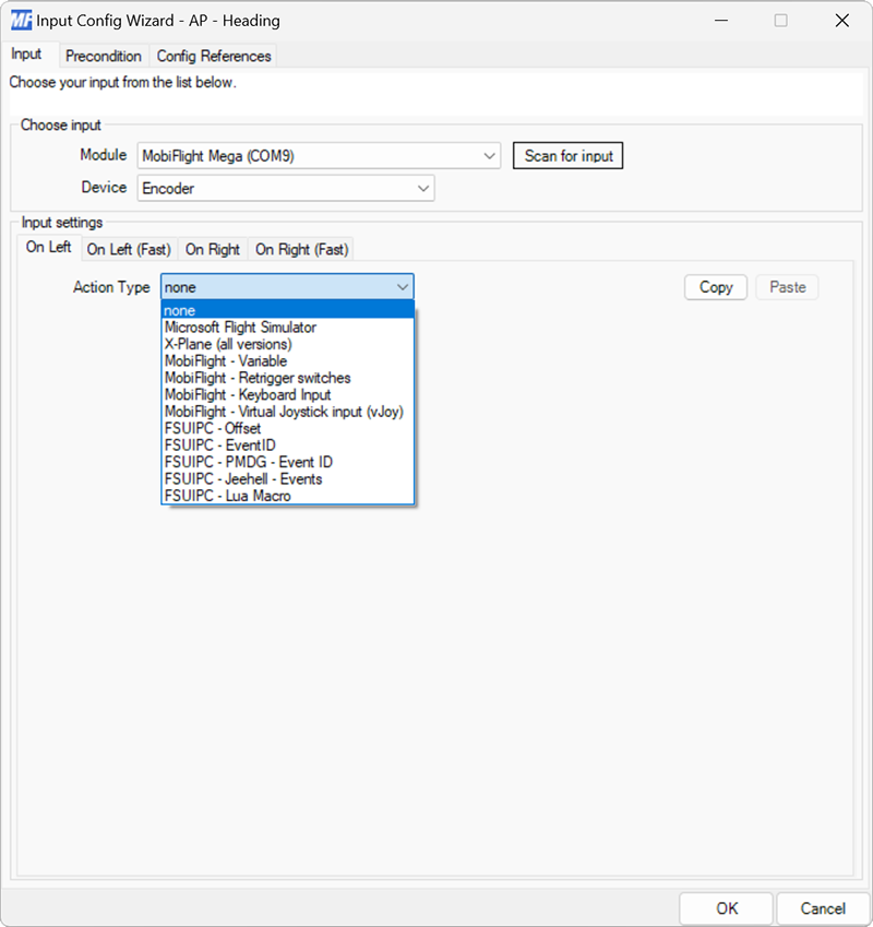
Input configuration
The On Left event fires when the encoder is turned to the left.
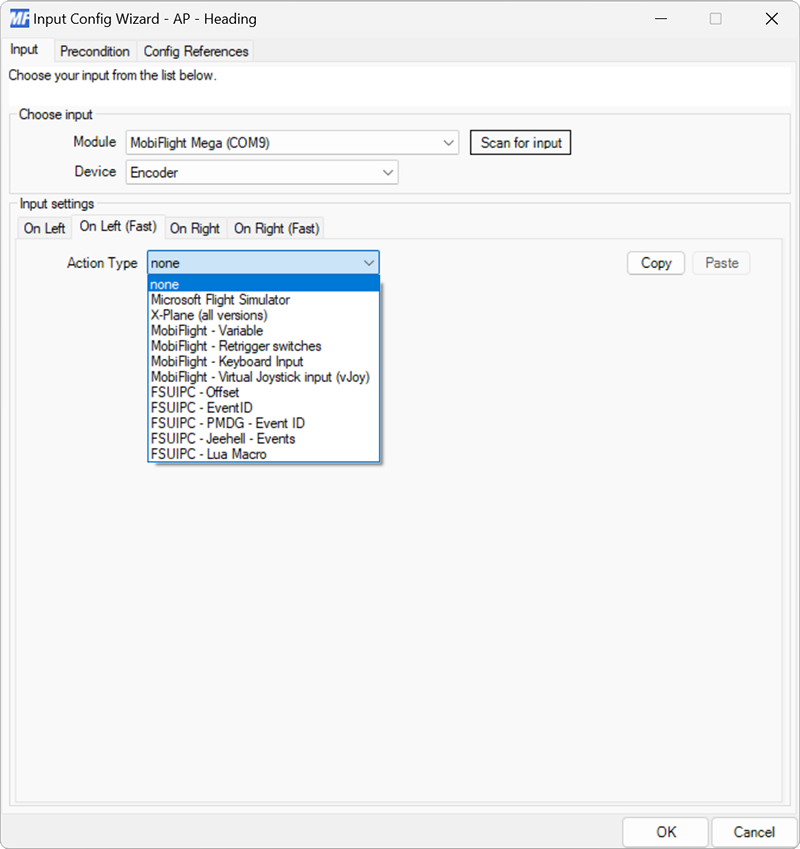
The On Left (Fast) event fires when the encoder is turned to the left quickly.
The On Right event fires when the encoder is turned to the right.

The On Right (Fast) event fires when the encoder is turned to the right quickly.
